
Installation of an ELIOS electric furnace compatible with R-454B in Mont-Saint-Hilaire, on Montreal’s South Shore
In Mont-Saint-Hilaire, AirGreen installs an ELIOS electric furnace integrated with an R-454B central heat pump, including ductwork modifications, electrical connection, and complete commissioning.
In summer, the outdoor unit rejects the house's heat outside.
Generic illustration of this type of installation, not a survey of this job site. Tap a number.
It captures or rejects heat outside. It sits on a level base, above the snow, with free space all around.
The insulated refrigerant lines enter the house through a sealed opening and run to the indoor coil.
A shut-off switch near the outdoor unit isolates it safely for service.
Sitting on the indoor module, it moves heat between the house air and the refrigerant.
Electric furnace or air handler: its fan pushes air through the ducts. The electric backup takes over in extreme cold.
Supply ducts bring air to the rooms; returns bring it back to the unit. Their condition matters as much as the unit's.
It protects the coil and the fan. A dirty filter cuts airflow, so it gets checked regularly.
It runs the heat pump and the backup heat. It must be compatible with the installed system.
A central integration completed in a tight mechanical space, with ductwork adaptation and complete system preparation
At Mont-Saint-Hilaire, we completed the installation of an ELIOS electric furnace integrated into a central system using R-454B refrigerant. The project required much more than simply replacing a heating unit: the new equipment had to be integrated with the existing air distribution system, duct transitions had to be adapted, condensate drainage had to be prepared, the electrical components had to be connected, and the furnace's operation had to be coordinated with the outdoor heat pump.
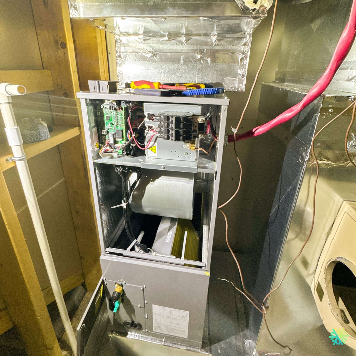
The photograph taken during the work shows the indoor unit with its service panel still removed. This step allows our technicians to access the circuit board, electrical protections, blower motor, and various connections required for commissioning.
The image also reveals a common constraint in homes on the South Shore: the mechanical room offers little clearance. The furnace is installed between a wooden structure and an existing network of metal ducts. Each connection must therefore be planned precisely to maintain reasonable access to the components, avoid air restrictions, and allow for future HVAC maintenance.
The objective was clear: to create a central system capable of providing uniform heating and cooling distribution throughout the home while maintaining a clean, safe installation suited to the building's actual conditions.
An electric furnace that plays several roles in the central system
In a central heat pump system, the electric furnace is not used solely to produce heat with electric elements. It also serves as the core of the home's air circulation system.
The indoor unit combines several important functions:
- it circulates air through the ducts;
- it distributes the heat produced by the heat pump;
- it distributes conditioned air during the summer;
- it can activate auxiliary electric heating when necessary;
- it receives commands from the thermostat;
- it manages different operating sequences;
- it protects certain components using controls and electrical devices.
The large cylindrical fan visible at the center of the unit is the centrifugal fan. Its role is to draw in return air, pass it through the filter and indoor coil, and then push the conditioned air into the duct system.
The fan speed must be adjusted according to the system capacity, the network’s static pressure, and the required airflow. An improperly configured fan can cause several problems:
- excessive noise at the grilles;
- insufficient airflow;
- low heat pump efficiency;
- uncomfortable cycles;
- ice formation on the coil in cooling mode;
- inadequate supply-air temperature in heating mode;
- higher electrical consumption.
At AirGreen, we therefore do more than simply power on the unit. We check how the furnace responds to the existing system and adjust its configuration when the system design allows it.
What the inside of the unit shows us
The removed front panel makes it possible to observe several essential components of this ELIOS electric furnace.
In the upper-left section, the electronic control board manages the signals from the thermostat and coordinates the various operating modes. It communicates with the blower motor, relays, safety devices, and, depending on the configuration, the outdoor unit.
In the upper central section, the modules and disconnect devices associated with the electric heating are accessible for connections and inspections. The electrical components of a central furnace may require a significant power supply. The sizing of the conductors, circuit breakers, and protective devices must therefore comply with the equipment nameplate and applicable electrical requirements.
The central section contains the fan. Its position facilitates access to the motor and blower wheel during service operations. Beneath the fan, the lower compartment and part of the unit’s internal structure can be seen.
The open panels visible in the image do not represent the installation’s final condition. They are temporarily removed to allow:
- connection of the power wires;
- connection of the low-voltage controls;
- terminal verification;
- fan configuration;
- visual inspection of the components;
- electrical measurements;
- validation of the startup sequences.
Once testing is complete, the panels must be properly reinstalled. Their purpose is not limited to protecting the wires. They also contribute to the cabinet’s airtightness and maintain the airflow path specified by the manufacturer.
Adapting to the existing duct network
Connecting a new furnace to existing ducts requires careful analysis. In this Mont-Saint-Hilaire installation, the network includes several metal sections and transitions fabricated to connect the unit to the existing distribution system.
Surfaces covered with aluminum tape seal the joints between duct sections. A poorly sealed network can lose some of the heated or cooled air before it even reaches the rooms.
These losses can occur in:
- joints between the ducts;
- transitions;
- access panels;
- connections around the unit;
- return ducts;
- passages through unconditioned spaces.
A leak on the supply side wastes air that has already been conditioned. A leak on the return side can draw in dust, moisture, or air from a mechanical room. In both cases, efficiency and air quality can be affected.
We also pay particular attention to the shape of the transitions. A piece of sheet metal that is too abrupt or restrictive can create turbulence, increase static pressure, and make the system noisy. A properly fabricated transition helps the blower distribute air more efficiently.
A project completed in a challenging mechanical space
Access around the furnace is limited by the framing, ducts, and other mechanical installations. This type of configuration requires more careful planning than an installation carried out in a large, open basement.
Our technicians must be able to:
- bring the equipment into the mechanical room;
- position it without damaging the ducts;
- keep the space needed to remove the panels;
- access the electrical connections;
- install the condensate drain;
- route the refrigerant piping;
- perform the tests;
- maintain sufficient clearance for future service.
The choice of furnace orientation is therefore important. A service door placed against a wall or duct can make certain repairs very difficult. We always seek to balance the room dimensions, the duct configuration, and the manufacturer's access requirements.
For this project, the unit was positioned vertically. This configuration suited the existing structure and allowed connection to the ducts located above and to the side.
The R-454B refrigerant and its role in the system
The R-454B is the refrigerant used in the heat pump circuit associated with this central system. It circulates between the outdoor unit and the indoor heat exchanger to transfer heat.
It is important to distinguish the functions of the two units:
- the outdoor heat pump contains, among other components, the compressor and outdoor coil;
- the indoor section contains the refrigeration coil;
- the electric furnace provides air circulation and auxiliary heating;
- the copper lines connect the indoor circuit to the outdoor circuit.
R-454B belongs to the A2L refrigerant category. Its use requires appropriate practices, compatible tools, and particular care during connection and commissioning.
Our work takes into account, in particular:
- equipment compatibility;
- ventilating the work area;
- the tightness of the refrigeration connections;
- using suitable tools;
- completely evacuating the circuit;
- checking the refrigerant charge;
- the absence of inappropriate ignition sources;
- instructions specific to the manufacturer.
However, the mention of R-454B alone does not make it possible to determine the system's exact capacity, seasonal efficiency, or eligibility for financial assistance. This information must be confirmed using the complete model numbers of the indoor and outdoor units, as well as the corresponding certified combination.
Condensate drainage: a detail that should never be improvised
The PVC piping visible to the left of the unit is part of the drainage work or the mechanical preparation around the system. In cooling mode, the indoor coil becomes cold and removes moisture from the air. This moisture turns into water in the condensate pan.
The water must then be drained in a controlled manner. A poorly designed drain can cause:
- an overflow;
- water around the furnace;
- damage to the floor or walls;
- a damp odor;
- mold growth;
- the system being shut down by a safety device;
- premature corrosion of the cabinet.
The drain slope, the quality of the connections, and accessibility for cleaning are essential. Depending on the home's configuration, a condensate pump may be necessary when gravity drainage is not possible.
We also verify that the pan is properly positioned and that water does not remain trapped in a section of the piping.
The electrical connection of a central furnace
An electric furnace imposes a much greater load than a simple fan. Its heating elements can operate in stages to add heat when the heat pump alone is insufficient to meet demand.
The choice of auxiliary heating capacity must be consistent with:
- the capacity of the electrical panel;
- the home's load calculation;
- the capacity of the conductors;
- the protections specified by the manufacturer;
- the building's heating requirements;
- the heat pump's expected operation.
Installing more powerful electric elements is not automatically preferable. Excessive power can significantly increase electrical demand and require major modifications to the electrical panel. However, insufficient power may limit backup capacity during very cold days or a defrost cycle.
The red conductors visible near the unit illustrate the importance of the power connection in this type of project. Before closing the panels, we check the tightness of the connections, compliance of the wiring, and the operating sequence of the elements.
Checks performed during commissioning
Commissioning a central system involves several checks. We must confirm that the heat pump, furnace, thermostat, and ductwork operate together properly.
Our checks may include:
- the furnace's response to a ventilation demand;
- indoor fan startup;
- heat pump control;
- the sequence of the electric heating elements;
- thermostat operation;
- the return-air temperature;
- the supply-air temperature;
- power consumption;
- the condition of the electrical connections;
- water drainage;
- the presence of vibrations;
- noise in the ductwork;
- the codes displayed on the control board;
- properly closing the panels.
The photograph also shows a digital display on the control board. These indicators allow technicians to confirm certain operating conditions and identify an issue more quickly during testing or a future service call.
Comfort, efficiency, and practical advice after installation
More even distribution throughout the home
A ELIOS central electric furnace paired with a heat pump can distribute air throughout all areas served by the ductwork. However, the comfort achieved depends on proper system balancing.
When a room receives too little air or one floor remains warmer than the other, you should not automatically conclude that the heat pump lacks capacity. The problem may be caused by a closed register, an undersized duct, insufficient return air, or excessive static pressure.
During our projects in Mont-Saint-Hilaire, Longueuil, Boucherville, Saint-Bruno-de-Montarville, and elsewhere on the South Shore, we regularly encounter ductwork designed for older systems. Its compatibility with new equipment must be verified rather than assumed.
Heat pump heating and electric backup
In a central configuration, the heat pump generally provides the main heat during a large part of the winter. The electric furnace can then provide backup or supplementary heat depending on the outdoor temperature, indoor demand, and thermostat programming.
Electric heating may operate, in particular:
- when a rapid temperature increase is requested;
- during certain very cold periods;
- during a defrost cycle;
- when the thermostat calls for an auxiliary stage;
- if the heat pump is temporarily unavailable.
Reasonable thermostat programming helps reduce unnecessary activation of the electric elements. Raising the setpoint abruptly by several degrees can, depending on the settings, immediately trigger the backup heat.
To limit consumption, it is generally preferable to maintain a stable setpoint or adjust the temperature gradually.
Mistakes to avoid when replacing an electric furnace
Ordering the unit without measuring the available space
The cabinet dimensions, panel positions, and duct routes must be checked before delivery. A few centimeters can make all the difference in a cramped mechanical room.
Reusing ducts without checking their capacity
A modern unit will not correct an improperly sized duct system. Airflow and static pressure must be considered during selection.
Neglecting the air return
A return that is too small can starve the blower, increase noise, and reduce performance. Air must be able to return to the furnace as easily as it is distributed.
Choosing the heating elements without checking the electrical panel
The backup heating capacity must comply with the available electrical capacity. Prior validation helps avoid surprises during the work.
Forgetting to allow access for maintenance
The panels, control board, motor, filter, and drain must remain accessible. An overly tight installation can increase the time and cost of future work.
Confusing the refrigerant, model, and capacity
The term R-454B indicates the type of refrigerant. It does not necessarily represent the furnace model number. To confirm the BTU rating, performance, and applicable programs, consult the complete rating plates.
Recommended maintenance to preserve the system
Regular maintenance helps maintain airflow and protect the components.
The homeowner should, in particular:
- inspect the filter monthly during periods of heavy use;
- replace the filter according to its condition and applicable recommendations;
- do not block the return grilles;
- keep the supply registers open, except when adjusted by a professional;
- monitor for water around the furnace;
- avoid storing objects against the panels;
- report any unusual noise, code, or odor promptly.
A filter that is too dirty forces the blower to work harder. It can also reduce airflow through the indoor heat exchanger and affect the heat pump’s operation.
During a professional HVAC maintenance service, we can inspect the blower wheel, motor, electronic control board, electrical components, connections, drainage, heat exchanger, temperatures, and the system’s overall operation.
Subsidy eligibility: verification through a certified combination
Certain central heat pumps may be eligible for financial assistance programs, depending on the criteria in effect and the exact combination of appliances installed.
Eligibility must never be assumed solely because the system uses R-454B or bears a particular brand. It depends, among other things, on:
- the outdoor unit model;
- the indoor unit model;
- the certified combination;
- the heating capacity;
- the declared performance;
- the building’s use;
- the program’s rules at the time of application.
Before presenting a subsidy amount, we verify the official references and complete model numbers. This method avoids creating false expectations and allows the owner to make an informed decision based on verifiable information.
AirGreen expertise applied to central systems
At AirGreen, we install and maintain electric furnaces, central heat pumps, air handling units, and central air conditioning systems in Greater Montréal.
We serve Montréal, Laval, Longueuil, Mont-Saint-Hilaire, the North Shore, and the South Shore, among other areas. Each project is assessed according to its building, rather than according to a one-size-fits-all formula.
For this ELIOS electric furnace installation in Mont-Saint-Hilaire, our work required precise coordination between:
- the indoor cabinet;
- the existing ductwork network;
- power supply;
- controls;
- refrigerant piping;
- drainage;
- the outdoor heat pump using R-454B.
The job-site image shows a unit that is still open, tools placed on the cabinet, and several connections in progress. This is the stage when our technicians verify details that will no longer be visible once the installation is complete.
A reliable central installation is built precisely at this stage: before the panels are closed, before the premises are handed over, and before the owner begins using their new system.
The care taken with the wiring, airflow, ductwork, and drainage directly affects everyday comfort. This comprehensive approach is what makes it possible to achieve a durable HVAC installation that is accessible for maintenance and adapted to the residence’s actual needs.
How it goes, from the first call to the end
The main steps of this kind of job at AirGreen. Every house has its quirks: the estimate brings them out.
We look at the ducts, the current indoor module, the electrical panel and the planned spot for the outdoor unit.
The equipment combination, capacity and price, in writing. We check whether the combination qualifies for assistance programs.
Access protected, old unit disconnected and removed when it is being replaced.
Electric furnace or air handler, with its coil, connected to the supply and return ducts.
On a level base, raised above the snow, with free space all around.
Insulated, they enter through a sealed opening and run to the indoor coil.
Dedicated circuits, accessible disconnect, a thermostat that works with the heat pump and the backup heat.
Leak test, vacuum, start-up, airflow check and a test of both modes.
Filter, thermostat, backup heat in extreme cold: what to know before winter.
- The on-site estimateWe look at the ducts, the current indoor module, the electrical panel and the planned spot for the outdoor unit.
- The quoteThe equipment combination, capacity and price, in writing. We check whether the combination qualifies for assistance programs.
- Getting readyAccess protected, old unit disconnected and removed when it is being replaced.
- The indoor moduleElectric furnace or air handler, with its coil, connected to the supply and return ducts.
- The outdoor unitOn a level base, raised above the snow, with free space all around.
- The refrigerant linesInsulated, they enter through a sealed opening and run to the indoor coil.
- Electrical and thermostatDedicated circuits, accessible disconnect, a thermostat that works with the heat pump and the backup heat.
- Tests and start-upLeak test, vacuum, start-up, airflow check and a test of both modes.
- The walkthroughFilter, thermostat, backup heat in extreme cold: what to know before winter.
And at your place?
Two quick checks with real numbers: what heat costs, and what your current heaters add up to in BTU/h.
Conversion: 1 W = 3.412 BTU/h. An indication, not a load calculation: baseboards and furnaces are often stronger than the real need, and they can stay as backup. AirGreen confirms the capacity on site.
What to do, season by season
Three habits per season for this unit. They take a few minutes and prevent many calls.
- Check the indoor module's filter.
- Clear winter debris from the outdoor unit.
- Test cooling before the heat arrives.
- Check the filter more often in peak season.
- Keep registers and returns clear.
- Watch condensate drainage near the coil.
- Change or clean the filter.
- Test heating and backup heat before the cold.
- Book periodic maintenance.
- Clear snow around the outdoor unit.
- Store nothing in front of the indoor module.
- Note any unusual noise or smell and call us.
Which type of equipment for your project?
Pick what looks like your need.
Four mistakes we do not make
Flip each card to see what we do instead.
What people ask us about this kind of work
Can I keep my current ducts?
What happens in extreme cold?
Furnace, air handler, ducted: what is the difference?
Are there grants?
Do I need a permit?
How much can I save?
How is the LogisVert assistance calculated?
Will my current thermostat work?
Central or wall units: which one?
Does AirGreen hold the required licences?
Is the estimate free?
No question matches. Write to us: we answer.
Useful pages for what comes next
More jobs to see, near you
By town, by equipment or by region: browse more than 4,700 published projects.
Each dot: a town where AirGreen has published projects. The glowing dot: this job.
Tell us about your house. We come and see it for free.
The on-site estimate is free and the quote follows within 24 hours.
Text and photo: a real AirGreen Climatisation & Chauffage job. The diagrams are generic illustrations of the type of installation, not a survey of this job site. Sources of the added figures: airgreen.ca product pages (NEEP / AHRI performance), Hydro-Québec (Heat pumps page, LogisVert, read on 13 October 2026), Régie de l’énergie (rate D as of 1 April 2026).