
Installation of an ELIOS Central-Elios R454B electric furnace in Sainte-Julie
In Sainte-Julie, AirGreen integrates an ELIOS R454B electric furnace into an existing central system, adapting the ductwork, electrical supply, controls, and A2L safety requirements.
- City
- Region
- Equipment
- Brand
- Challenges
- Published
The job on one screen
The article, chapter by chapter
A complete adaptation of the central system in a complex mechanical space on the South Shore
This ELIOS Central-Elios electric furnace installation with R454B in Sainte-Julie represents exactly the type of project where quality workmanship is measured by more than just the installed unit. The real challenge was integrating a new central indoor unit into an existing mechanical room already occupied by an extensive duct network, multiple controls, electrical connections, and control components from the previous configuration.
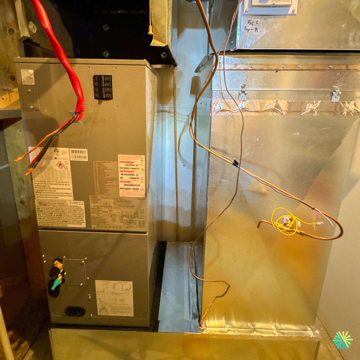
The photo taken during the work clearly shows the reality of the worksite. The ELIOS cabinet was positioned to the left of a large metal return-air duct. Several control wires were still being connected, the heavy-gauge electrical lines were being prepared to power the heating section, and the system had to be adapted to the existing ductwork without compromising airflow.
The installed unit is the indoor section of a central cold-climate heat pump system. Homeowners often use the term “electric furnace” to refer to this cabinet because it may include an auxiliary electric heating element. Technically, it is also an air handler or air-handling unit, responsible for circulating air throughout the home, transferring heat from the heat pump, and activating electric heating when demand requires it.
The refrigerant R454B circulates through the refrigeration circuit connecting the indoor unit to the outdoor condenser. This fluid is not found in the electric heating elements themselves, but it is an integral part of the installed Central-Elios system.
What the photo reveals about the worksite
The image makes it possible to identify several important technical components:
- the ELIOS indoor cabinet installed vertically;
- the A2L pictogram associated with R454B refrigerant;
- a large return-air duct located on the right;
- sheet-metal transitions fabricated to connect the unit to the existing ductwork;
- several control cables being connected;
- a high-capacity electrical supply line;
- a coil or filtration section integrated into the system;
- an especially narrow mechanical space;
- a shared metal base supporting the different sections;
- duct joints sealed with metal tape.
This type of project requires precise coordination between the mechanical, electrical, refrigeration, and air-distribution systems. An error in any of these areas can reduce the overall performance, even if the selected equipment is efficient.
Why the mechanical space was the main challenge
In a new construction, we can generally plan the ductwork around the equipment. In an existing home in Sainte-Julie, the situation is often reversed: we must select, position, and adapt the new equipment around an existing network.
In this project, the large duct located on the right occupied a considerable portion of the available width. The ELIOS cabinet therefore had to be installed beside it while maintaining:
- front access to the panels;
- sufficient clearance for the connections;
- the ability to replace the filter;
- an airtight air transition;
- a safe path for the cables;
- future access to the mechanical components;
- a stable, properly leveled base.
A furnace that physically fits in the space is not necessarily a properly installed furnace. It must be possible to open the panels, test the components, and remove the blower motor without having to demolish the ductwork.
A central system range from 24,000 to 60,000 BTU
The Central-Elios range includes 24,000, 30,000, 36,000, 48,000, and 60,000 BTU/h combinations. The corresponding indoor models are designed to operate with the associated outdoor units in the same range.
Cabinet dimensions vary according to capacity:
- approximately 17.52 in. wide for the 24,000 BTU model;
- approximately 21.02 in. for the 30,000 and 36,000 BTU models;
- approximately 24.49 in. for the 48,000 and 60,000 BTU models.
The nominal depth is approximately 21.02 in., while the height varies from approximately 45 to 52.99 in., depending on the model. These differences may seem minor on paper, but they become critical in a mechanical room as tight as the one shown in the photo.
The precise capacity of this system cannot be confirmed from the image alone, since the characters on the nameplate are not legible enough. The actual sizing must be determined from the model numbers and the building load calculation.
Integration with the existing ductwork
The ductwork system plays a role just as important as the furnace itself. The heat pump can produce the required heat or cooling, but this energy must then be distributed properly throughout all the rooms.
In this installation in Sainte-Julie, the main air return is on the right. We had to adapt the connection between this existing duct and the new ELIOS cabinet.
Maintaining sufficient airflow
An undersized air return limits fan airflow. The system must then work against excessive pressure, which can cause:
- increased noise;
- reduced airflow at the registers;
- an irregular discharge-air temperature;
- overheating of the electric elements;
- a frozen coil in cooling mode;
- increased consumption;
- premature motor wear.
We must therefore maintain a duct cross-section suitable for the installed capacity. Transitions must be gradual enough to avoid creating an abrupt restriction.
Sealing the joints
The strips of metal tape visible in the photo are used to seal certain ductwork joints. An air leak in a mechanical room represents a direct loss of heating or cooling.
On the return side, a leak can also draw in:
- dust;
- unconditioned air;
- odors;
- particles from the mechanical room.
We therefore check the airtightness of the plenum, transitions, panels, and base.
Auxiliary electric heating
The Central-Elios range can be combined with auxiliary electric coils ranging from 3 to 25 kW.
These components do not necessarily replace the heat pump. Rather, they supplement its operation when heating demand becomes high.
Auxiliary heating may operate:
- during certain periods of intense cold;
- when the indoor temperature needs to rise quickly;
- during part of the defrost cycle;
- if the outdoor unit is temporarily unavailable;
- when the building load exceeds the heat pump’s instantaneous capacity.
The power rating must be selected carefully. A rating that is too low may not meet heating needs in extreme temperatures. A rating that is too high may require a substantial electrical supply and increase power demand.
The large-gauge electrical cables visible in the photo
The red cable visible to the left of the cabinet is connected to the power supply. Its presence shows that installing electric heating involves a much more substantial circuit than the simple control wiring of a thermostat.
Before the final connection, we must verify:
- the capacity of the electrical panel;
- the conductor rating;
- the capacity of the electric coil;
- the number of circuits required;
- the circuit breaker ratings;
- grounding;
- the requirements listed on the nameplate;
- the tightening of the connections.
We can never assume that the old wiring is automatically suitable for the new furnace. Even if the appliance replaces an existing electric system, the power, connection method, or number of circuits may be different.
The control wires and system logic
Several low-voltage wires are visible around the main duct. They transmit commands between the thermostat, indoor unit, outdoor unit, and accessories.
These connections can control:
- the heating demand;
- air conditioning;
- the fan;
- activation of the auxiliary heating;
- communication with the heat pump;
- certain safety devices;
- the alarm signals.
A wiring error can cause incomplete operation: auxiliary heating may not start, the fan may remain stopped, the heat pump may not modulate correctly, or a safety alert may be triggered.
We therefore follow the wiring diagram specific to the installed model rather than relying on an approximate color code. A wire’s color never guarantees its function.
The Central-Elios system using R454B: efficiency, safety, and cold-climate performance
A heat pump designed to operate down to -30 °C
The Central-Elios range is designed for the Canadian climate. The manufacturer indicates a heating operating range down to -30 °C. At this temperature, the systems retain approximately 69% to 76% of their rated heating capacity, depending on the model.
The documentation also indicates a capacity of up to 100% of the rated value at -20 °C. This data helps reduce the use of electric heating compared with a system that quickly loses capacity as the temperature drops.
Nevertheless, the machine’s capacity must be distinguished from the home’s actual needs. A heat pump can continue operating at -30 °C without necessarily covering all of the building’s heat losses on its own.
In Sainte-Julie, sizing must take into account:
- the heated area;
- insulation;
- airtightness;
- the number of windows;
- exposure to wind;
- the interior volume;
- the duct configuration;
- of the desired indoor temperature.
Inverter technology and modulation
The Central-Elios heat pump uses an inverter compressor. It can vary its speed according to demand.
Instead of switching only between off and full power, the system can operate at a lower output when demand is moderate. This modulation helps:
- maintain a more stable temperature;
- reduce short cycles;
- improve comfort;
- reduce noise at partial load;
- limit certain current surges;
- adjust production to actual demand.
However, outdoor modulation must be accompanied by proper indoor airflow adjustment. Improper airflow can negate some of the benefits of Inverter technology.
Range energy performance
Depending on capacity, the range reaches up to 18.3 TRÉS2 in cooling and up to 8.6 CPSC2 in Region V in heating. COP at 8.3 °C ranges from approximately 3.1 to 3.65, depending on the model.
A COP of 3 means, simply, that the system transfers approximately three units of heat for every unit of electricity used under the measured conditions. However, performance varies with outdoor temperature, compressor speed, and the condition of the installation.
The combinations presented in the documentation are identified as ENERGY STAR 6.1 and ENERGY STAR Cold Climate.
Rebates: why the exact model remains essential
ENERGY STAR Cold Climate certification may be relevant for certain financial assistance programs. However, it does not automatically guarantee eligibility.
The following must be verified:
- the exact indoor model;
- the exact outdoor model;
- the certified combination;
- the AHRI reference or requested identifier;
- the capacity recognized by the program;
- the criteria in effect on the installation date;
- the type of building;
- the required documents.
In this project, the photo does not show the model clearly enough to identify it accurately. Therefore, no rebate amount should be announced based on the image alone.
R454B and the A2L classification
The A2L pictogram is clearly visible on the front of the cabinet. It indicates that the system uses R454B refrigerant, classified as mildly flammable.
This classification requires specific procedures:
- using tools compatible with A2L refrigerants;
- checking ignition sources;
- conducting a leak-tightness test;
- performing a thorough vacuum evacuation;
- ensuring adequate ventilation during the work;
- observing charge limits;
- reinstalling all panels;
- checking the safety devices.
R454B must not be handled as though the equipment automatically used the same procedures as an older R410A system.
Integrated leak detection
The Central-Elios documentation describes an integrated leak detection sensor. If a leak is detected, the system can stop the compressor, maintain air circulation, and transmit a service alert.
Keeping the fan running helps disperse the refrigerant and is part of the safety strategy specified by the manufacturer.
For this function to be effective, you must:
- install the sensor in the specified location;
- follow the wiring;
- keep compatible components;
- do not modify the cabinet arbitrarily;
- check the sequence during commissioning.
Refrigerant lines to be validated
For the combinations shown in the technical data sheet, the specified diameters are:
- 3/8 in. on the liquid side;
- 3/4 in. on the gas side.
The maximum length is 164 ft for the 24,000 and 30,000 BTU models, then 246 ft for the 36,000 to 60,000 BTU models. The maximum height difference ranges from 82 to 98.4 ft, depending on the capacity.
When replacing the system, we must therefore inspect the existing lines before deciding to keep them.
The items to be checked include:
- the diameter;
- the length;
- the interior cleanliness;
- the condition of the copper;
- the insulation;
- the old brazed joints;
- the routing;
- the elevation difference.
Condensate drainage
Even if the drain is not clearly visible in this photo, it remains an essential part of the indoor installation.
In air conditioning, the coil removes moisture from the air. The dehumidification capacity indicated in the documentation ranges from approximately 2.05 to 5.87 liters per hour, depending on the model.
This water must be drained without leaks or standing water.
An improperly installed drain can lead to:
- water damage;
- cabinet corrosion;
- odors;
- an overflowing drain pan;
- a safety shutdown;
- damage to the floor or the ceiling below.
We check the slope, airtightness, and drainage before completing commissioning.
Mistakes to avoid in an existing central installation
Reduce the return-air cross-section excessively
A transition that is too small can starve the fan and increase static pressure.
Leave the wires unidentified
During a future service call, unidentified wiring increases the risk of error.
Install an electrical component without calculating the load
The available power at the panel must be confirmed before installation.
Block the cabinet panels
The components must remain accessible for maintenance.
Reuse refrigerant lines without inspection
The diameter and condition must be compatible with the R454B system.
Neglect duct airtightness
A leak reduces the airflow delivered to the rooms and increases losses.
Choose the capacity based solely on the floor area
The calculation must also account for heat loss and the distribution network.
Modify the A2L safety system
The sensors, controls, and panels must be installed according to the manufacturer's instructions.
Commissioning before closing the panels
Once all connections are complete, we carry out a series of checks.
Electrical checks
We inspect:
- voltage;
- circuit breakers;
- current;
- tightness;
- grounding;
- the auxiliary heating sequences.
Refrigeration checks
We confirm:
- tightness;
- vacuum quality;
- the charge;
- temperatures;
- operating stability.
Airflow checks
We measure or check:
- airflow;
- static pressure;
- return-air temperature;
- supply-air temperature;
- noise;
- vibrations.
Control checks
We test:
- the thermostat;
- heating and cooling modes;
- the fan;
- auxiliary heating;
- communications;
- the safety alerts.
An installation designed to facilitate the next maintenance visit
The cabinet was positioned to preserve front access. This decision may seem simple, but it offers significant long-term value.
During HVAC maintenance, the technician may need to:
- remove a panel;
- test a relay;
- inspect the motor;
- check the electrical components;
- access the control board;
- check the R454B sensor;
- measure the airflow;
- clean the drain.
An installation that is too cramped or poorly oriented increases the time required for each service visit and can make certain repairs unnecessarily complex.
A custom adaptation carried out in Sainte-Julie
This ELIOS Central-Elios R454B electric furnace installation in Sainte-Julie shows why a central replacement requires a complete analysis of the building.
We had to work with a large existing return-air opening, limited mechanical space, a substantial electrical supply, multiple control wires, and sheet-metal transitions that needed to be adapted. The new unit had to integrate with the existing infrastructure while meeting the requirements specific to R454B.
At AirGreen, we apply this same rigor to our projects involving the installation of electric furnaces and central heat pumps in Montreal, Laval, Longueuil, the North Shore, and the South Shore.
Our work does not consist of installing a metal box near a duct. We must create a cohesive system in which the heat pump, electric furnace, fan, ductwork, thermostat, drainage, and electrical supply work together.
It is this coordination that makes it possible to achieve stable heating, uniform cooling, better-controlled energy consumption, and equipment that remains accessible for years to come.
The job tools
Two quick checks with real numbers: what heat costs, and what your current heaters add up to in BTU/h.
Conversion: 1 W = 3.412 BTU/h. An indication, not a load calculation: baseboards and furnaces are often stronger than the real need, and they can stay as backup. AirGreen confirms the capacity on site.
How the job unfolds
The main steps of this kind of job at AirGreen. Every house has its quirks: the estimate brings them out.
We look at the ducts, the current indoor module, the electrical panel and the planned spot for the outdoor unit.
The equipment combination, capacity and price, in writing. We check whether the combination qualifies for assistance programs.
Access protected, old unit disconnected and removed when it is being replaced.
Electric furnace or air handler, with its coil, connected to the supply and return ducts.
On a level base, raised above the snow, with free space all around.
Insulated, they enter through a sealed opening and run to the indoor coil.
Dedicated circuits, accessible disconnect, a thermostat that works with the heat pump and the backup heat.
Leak test, vacuum, start-up, airflow check and a test of both modes.
Filter, thermostat, backup heat in extreme cold: what to know before winter.
- The on-site estimateWe look at the ducts, the current indoor module, the electrical panel and the planned spot for the outdoor unit.
- The quoteThe equipment combination, capacity and price, in writing. We check whether the combination qualifies for assistance programs.
- Getting readyAccess protected, old unit disconnected and removed when it is being replaced.
- The indoor moduleElectric furnace or air handler, with its coil, connected to the supply and return ducts.
- The outdoor unitOn a level base, raised above the snow, with free space all around.
- The refrigerant linesInsulated, they enter through a sealed opening and run to the indoor coil.
- Electrical and thermostatDedicated circuits, accessible disconnect, a thermostat that works with the heat pump and the backup heat.
- Tests and start-upLeak test, vacuum, start-up, airflow check and a test of both modes.
- The walkthroughFilter, thermostat, backup heat in extreme cold: what to know before winter.
What we check on a job like this one
Each number is a point we check on site. Switch between summer and winter to watch air and heat move.
In summer, the outdoor unit rejects the house's heat outside.
Generic illustration of this type of installation, not a survey of this job site. Tap a number.
It captures or rejects heat outside. It sits on a level base, above the snow, with free space all around.
The insulated refrigerant lines enter the house through a sealed opening and run to the indoor coil.
A shut-off switch near the outdoor unit isolates it safely for service.
Sitting on the indoor module, it moves heat between the house air and the refrigerant.
Electric furnace or air handler: its fan pushes air through the ducts. The electric backup takes over in extreme cold.
Supply ducts bring air to the rooms; returns bring it back to the unit. Their condition matters as much as the unit's.
It protects the coil and the fan. A dirty filter cuts airflow, so it gets checked regularly.
It runs the heat pump and the backup heat. It must be compatible with the installed system.
Is your home ready?
Check what applies at your place. A "no" is not a refusal: it is what we sort out during the estimate.
Good habits, once the unit is in place
Six simple habits that keep the unit going. Your list stays on this device.
What to do, season by season
Three habits per season for this unit. They take a few minutes and prevent many calls.
- Check the indoor module's filter.
- Clear winter debris from the outdoor unit.
- Test cooling before the heat arrives.
- Check the filter more often in peak season.
- Keep registers and returns clear.
- Watch condensate drainage near the coil.
- Change or clean the filter.
- Test heating and backup heat before the cold.
- Book periodic maintenance.
- Clear snow around the outdoor unit.
- Store nothing in front of the indoor module.
- Note any unusual noise or smell and call us.
The right pages, at the right time
Four statements: true or false?
It all comes down to details you have just seen.
1. A central heat pump uses the house's ducts.
It connects to the existing ducts to heat and cool everywhere.
2. In extreme cold, electric backup heat can take over.
The indoor module (furnace or air handler) works with the heat pump and takes over in extreme cold.
3. The filter only gets changed when the unit breaks down.
A dirty filter cuts airflow. It gets checked regularly.
4. You can reuse the old unit's size without checking.
The house may have changed: insulation, windows, added rooms. Capacity is confirmed on site.
0 / 4 right answers
What people ask us about this kind of work
Can I keep my current ducts?
What happens in extreme cold?
Furnace, air handler, ducted: what is the difference?
Are there grants?
Do I need a permit?
How much can I save?
How is the LogisVert assistance calculated?
Will my current thermostat work?
Central or wall units: which one?
Does AirGreen hold the required licences?
Is the estimate free?
No question matches. Write to us: we answer.
More jobs to see, near you
By town, by equipment or by region: browse more than 4,700 published projects.
Each dot: a town where AirGreen has published projects. The glowing dot: this job.
An on-site estimate, the right capacity, the right equipment.
The on-site estimate is free and the quote follows within 24 hours.
Text and photo: a real AirGreen Climatisation & Chauffage job. The diagrams are generic illustrations of the type of installation, not a survey of this job site. Sources of the added figures: airgreen.ca product pages (NEEP / AHRI performance), Hydro-Québec (Heat pumps page, LogisVert, read on 13 October 2026), Régie de l’énergie (rate D as of 1 April 2026).