
Installation of a Hitachi airHome 400 wall-mounted heat pump with concealed indoor routing in Verdun, Montreal
In Verdun, AirGreen installs a Hitachi airHome 400 wall-mounted heat pump with a long, protected indoor run near the ceiling, a carefully executed flexible transition, and planned drainage for a reliable finish.
In summer, the outdoor unit rejects the house's heat outside.
Generic illustration of this type of installation, not a survey of this job site. Tap a number.
Mounted level on a wall plate, high enough for the air to reach the whole room, with enough space around it to slide the filters out easily.
The refrigerant lines, the communication cable and the drain go through the wall in a single opening, sealed against water, cold air and insects.
Two insulated copper pipes connect the two units. Outside, a line cover can protect them from sun, knocks and weather.
A shut-off switch near the outdoor unit isolates it safely for service. It must stay accessible at all times.
The compressor and the fan. In heating mode it captures heat from the outdoor air, even in winter, and moves it inside.
On the ground or on the wall, it keeps the unit above accumulated snow. The unit stays clear and defrost water can drain away.
The fan needs to blow freely. Storage, a fence or a wall too close, and efficiency drops while noise goes up.
An exposed line route, carefully integrated into the upper part of the room
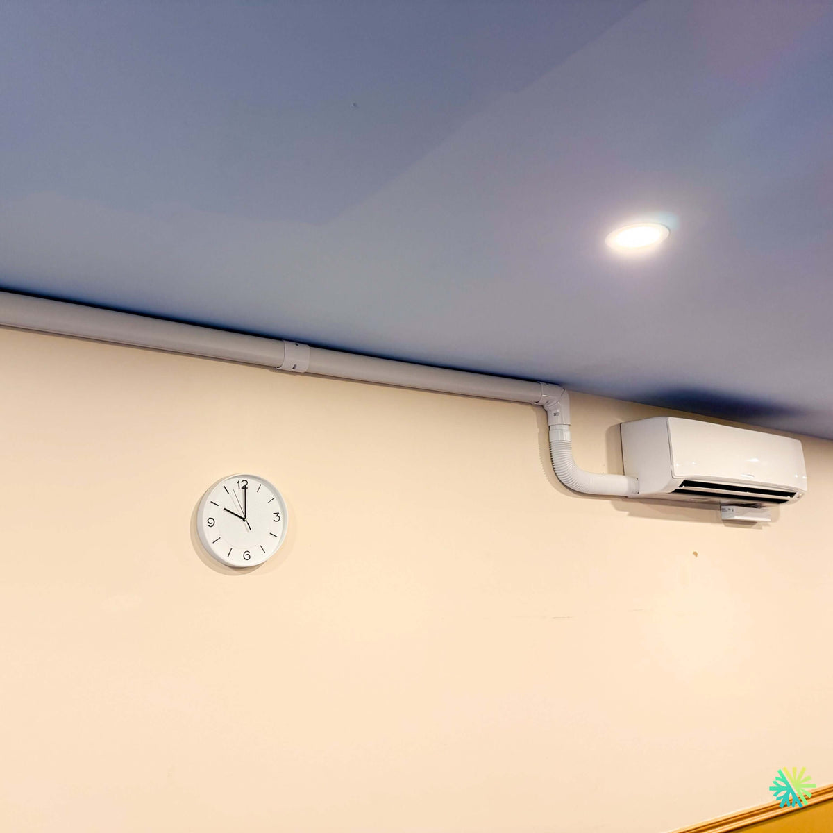
This wall-mounted heat pump installation in Verdun stands out because of a technical element that is immediately visible: the connections could not exit directly behind the indoor unit. Our AirGreen team therefore created a protected horizontal route installed near the ceiling to neatly run the lines to the Hitachi airHome 400.
In many Verdun apartments, the location offering the best air distribution does not always correspond to the wall directly facing the exterior. The building’s structure, room layout, the presence of shared walls, and the available path to the outdoor unit may require a longer indoor route.
In this project, the unit was installed in the upper-right section of the wall. A white line-set cover runs along the ceiling before changing direction toward the unit. The final section connects to the left side of the heat pump with a flexible white conduit, providing a compact transition between the rigid route and the unit’s connections.
The finish remains deliberately understated:
- the line-set cover is placed against the junction between the wall and the ceiling;
- its white color blends with the ceiling and the indoor unit;
- the connections are grouped together instead of being left separately on the wall;
- the change in direction is made with suitable finishing pieces;
- the heat pump remains accessible for cleaning and servicing.
The result shows that an exposed indoor route can remain orderly when it is planned from the outset rather than improvised after the unit has been mounted.
Why couldn’t the lines simply run behind the unit?
When a heat pump is installed directly on an exterior wall, it is often possible to drill behind or immediately beside the indoor unit. The refrigerant line set then passes through the wall over a short distance before reaching the outdoor unit.
However, this scenario is not always possible. In a Verdun property, several constraints can alter the routing:
- the unit must be installed on an interior wall to better cover the room.
- the wall behind the unit may be a shared wall;
- the corresponding outdoor location may be inaccessible;
- a balcony, structure, or architectural obstacle may prevent a direct exit;
- the drain must reach another drainage point;
- the shortest route is not necessarily the most attractive or safest;
- the homeowner wants to avoid drilling through a specific section of the building.
In this installation, the route to the exit point required a lateral shift. We therefore grouped the bundle in a pipe cover installed high up, where it interferes least with the room’s everyday use.
What the technical route normally contains
The visible cover is not used solely to conceal two pipes. Depending on the exact system configuration, the route may contain:
- the liquid refrigerant line;
- the gas refrigerant line;
- the insulation around the cold line;
- the communication cable between the units;
- certain electrical conductors;
- the condensate drain;
- the support and protective materials.
Each component serves a distinct function. The refrigerant lines carry refrigerant between the indoor and outdoor units. The wiring provides power or communication, depending on the system design. The drain removes the water produced during cooling and dehumidification.
Grouping them in a cover protects these elements from impacts and provides a much more uniform finish than leaving a wrapped bundle directly on the wall.
A pipe cover installed near the ceiling to free up the wall
The horizontal route was placed as high as possible. This position offers several practical advantages:
-
It frees up the lower wall surface.
The homeowner retains the space for furniture, frames, shelves, or other uses. -
It reduces the visual impact.
The eye is generally less drawn to a cover installed at the junction of the wall and ceiling than to a conduit located in the center of the wall. -
It protects the route.
The lines are less exposed to impacts, moving furniture, or everyday activities. -
It facilitates certain changes in direction.
The route can follow the existing architectural lines and reach the unit via a short drop. -
It maintains reasonable access.
The cover sections can be opened during maintenance or future modifications.
The photo also shows several joints between the cover sections. These connections are necessary when the route exceeds the length of a straight piece or when an adjustment is needed to follow the wall precisely.
The flexible transition near the unit
The final section of the route is made with a flexible corrugated cover. This section connects to the side of the heat pump while absorbing the slight offset between the rigid cover and the entry point into the unit.
A transition of this type can be useful when:
- the unit is very close to the ceiling;
- the space available for a rigid elbow is limited;
- the lines must enter from the side;
- the actual angle does not correspond exactly to a standard fitting;
- we must avoid applying excessive pressure to the connections behind the housing.
This flexibility does not mean that the indoor lines can be bent freely. The copper pipes must follow an appropriate bend radius to prevent crushing or restricting the refrigerant flow.
We must also ensure that the transition does not press against the housing or transmit vibration to the wall.
The drain slope in a horizontal route
One of the most important aspects of a long indoor route is managing the condensate drain.
In air conditioning, humid room air passes through the cold coil. The moisture condenses, falls into the drain pan, and must then be removed. When drainage operates by gravity, the drain must maintain a sufficient slope along its entire length.
A cover can appear perfectly horizontal to the eye while containing a slightly sloped drain. This detail must be planned before closing the cover.
An improper slope can cause:
- water accumulation in the pipe;
- gurgling noises;
- backflow toward the indoor unit;
- odors;
- the formation of deposits;
- a leak on the wall;
- unnecessary strain on a condensate pump, if a pump is used.
During commissioning, we check the drainage rather than assuming that the drain is working. A water test confirms that the pan drains properly and that no section of the route is retaining condensate.
Why the unit is placed to the right rather than in the center of the wall
Aesthetically centering it is not always the best choice for an HVAC installation. The main objective is to direct air toward the occupied area and choose a location compatible with the conduits, structure, and maintenance.
In this project, the Hitachi airHome 400 is installed toward the right end of the wall. This positioning allows:
- to shorten the transition between the duct and the unit;
- to avoid an additional route;
- to direct the airflow toward the open part of the room;
- to keep the center of the wall available;
- to reduce the number of changes in direction;
- to create a continuous technical route.
The clock visible on the wall also helps convey the scale of the project: the heat pump remains relatively compact despite the necessary connections.
Essential upper clearance for air intake
The indoor unit primarily draws air through its upper section. It must therefore maintain clearance compatible with the manufacturer's requirements.
A heat pump installed too close to the ceiling could experience:
- reduced airflow;
- a less representative reading of the room temperature;
- increased noise;
- a loss of performance;
- difficult access to the filters;
- limited opening of the front panel.
In this installation, the unit is mounted high up but remains separate from the ceiling. The front panel remains accessible, and the lower louver has enough space to open and direct the air.
A Hitachi airHome 400 selected for year-round, modulated comfort
A range available from 9,000 to 36,000 BTU/h
The Hitachi airHome 400 is available in several capacities. The manufacturer's brochure specifically lists 9,000, 12,000, and 18,000 BTU/h systems, as well as 24,000 and 36,000 BTU/h categories.
The precise capacity of the unit visible in the photo cannot be confirmed without reading its model number. We therefore avoid assigning it an arbitrary capacity.
The choice of BTUs should be based on an analysis that takes several factors into account:
- the area of the zone;
- ceiling height;
- the quality of the insulation;
- the windows;
- solar exposure;
- the floor of the dwelling;
- the number of exterior walls;
- openings to adjacent rooms;
- heating use;
- the capacity of the existing heating system.
A larger unit does not automatically provide better comfort. An oversized system can quickly reach the desired temperature, then excessively shorten its operating periods. In air conditioning, this can impair humidity control.
An undersized unit may, on the other hand, run continuously during the most demanding conditions.
Dimensions that vary according to capacity
The 9,000 and 12,000 BTU models in the airHome 400 series use an indoor unit approximately 30.71 in wide, 11.02 in high, and 8.74 in deep. The 18,000 BTU model is approximately 37.40 in wide, while the larger units reach approximately 41.34 in and 43.3 in.
These differences directly affect:
- the choice of wall;
- the position of the line-set cover;
- clearances;
- the length of the flexible transition;
- access to the front panel;
- the range of the airflow.
Hitachi documentation also indicates efficiencies of up to 20.0 TRÉS2, CPSC2 values that vary by model and climate region, heating operation down to approximately -20.5 °C, and the use of R32 refrigerant.
Vector DC Inverter technology
The Hitachi airHome 400 uses a modulating compressor technology called Vector DC Inverter.
A conventional unit operating only in cycles starts at full capacity, stops, and then restarts when the temperature moves away from the setpoint. An Inverter heat pump can adjust its speed and reduce its capacity when demand decreases.
This modulation helps to:
- maintain a more stable temperature;
- reduce sudden fluctuations;
- limit frequent startups;
- improve acoustic comfort;
- adjust consumption to the actual load;
- maintain more consistent dehumidification.
In a room like the one in this project, the heat pump can therefore increase its capacity at startup, then slow down once the desired temperature is reached.
Sound levels suited to occupied spaces
The 9,000 and 12,000 BTU models can reach an indoor sound level of 29 dB(A) in quiet mode, according to the manufacturer's data. Higher-capacity models have different sound levels.
However, acoustic performance also depends on the installation work.
A long indoor run must be properly secured to prevent:
- movement of the lines;
- friction against the cover;
- vibrations at the joints;
- resonance in the duct;
- noise transmitted through the wall;
- pressure from the bundle against the unit.
We therefore check the attachment of the line-set cover, the position of the lines, the contact points, and the engagement of the unit on its mounting plate.
FrostWash to help maintain the heat exchanger
The airHome 400 series features FrostWash technology. It uses a freezing and thawing process on the indoor heat exchanger to help capture and remove certain accumulated impurities.
The manufacturer describes a comparative test in which a unit equipped with FrostWash maintained its airflow performance better than a comparison unit without this feature.
However, FrostWash remains a maintenance-assistance feature. It does not replace:
- cleaning the filters;
- inspecting the drain pan;
- cleaning the blower wheel;
- checking the drain;
- professional maintenance when significant deposits are present.
Mold Guard and residual moisture
The Mold Guard function is designed to reduce moisture that remains in the unit after certain cycles. It circulates air through the internal components and may heat the coil depending on the programmed cycle.
This function helps limit conditions that promote odors or mold growth, but it does not eliminate existing contamination.
To keep the heat pump in good condition, we recommend:
- clean the filters regularly;
- check the drain if you hear water noises;
- monitor for unusual odors;
- not to spray household cleaner into the unit;
- have the blower wheel cleaned when buildup is visible;
- not to block the upper air intake.
The airHome 400 design also includes removable side covers, a drain connection that can be configured on the left or right, a removable drain pan, and simplified access to certain components. These details make future service easier.
PM2.5 and activated carbon filter
The range includes a stainless steel prefilter and an activated carbon PM2.5 purification filter. This system helps treat the air passing through the unit and reduce certain particles or odors.
However, it is important to keep expectations realistic. A wall-mounted heat pump does not replace a central filtration system or an air exchanger. It primarily affects the air circulating in the area where it is installed.
In an urban neighborhood such as Verdun, the frequency of filter cleaning may vary depending on:
- proximity to traffic;
- the presence of pets;
- nearby construction work;
- cooking activity;
- the number of occupants;
- the number of operating hours.
Control options
The remote control lets you adjust the temperature, operating mode, fan speed, and airflow direction.
Depending on the selected combination and accessories, the Hitachi airHome 400 can also be equipped with a Wi-Fi adapter compatible with airCloud Go. Available features may include:
- remote control;
- weekly scheduling;
- certain consumption estimates;
- mode changes;
- ventilation control;
- compatibility with certain voice controls.
The airPoint Room H700 wall controller is also available as an option for certain applications. These accessories must be confirmed when preparing the quote.
A longer route requires rigorous commissioning
The length and configuration of the route affect the preparation of the refrigerant lines. Maximum limits vary according to the system capacity.
The documentation indicates, among other things, maximum total lengths ranging from approximately 82 ft for some smaller models to 165 ft for the largest combination presented. The permissible height difference also varies by model.
These values represent technical limits, not a recommendation to systematically use the maximum length.
During commissioning, we must verify:
- the actual line length;
- required diameters;
- flaring;
- torque specifications;
- tightness;
- evacuation;
- the additional charge, when required;
- communication between the units;
- condensate drainage;
- discharge temperatures.
Small models generally use a 1/4-inch liquid line and a 3/8-inch gas line. Higher capacities require larger lines. The diameter should never be chosen solely based on what is available on the job site.
Evacuation: essential after installing the lines
Before releasing the refrigerant from the outdoor unit, the air and moisture present in the lines must be removed using a vacuum pump.
A circuit contaminated by moisture can cause:
- abnormal pressures;
- reduced performance;
- reactions with the compressor oil;
- the formation of contaminants;
- premature wear;
- problems that are difficult to diagnose.
This step is invisible in the final photo, but it is one of the elements that distinguish a quick installation from a professional heat pump installation.
Grants: verify the models, not just the airHome 400 name
The brochure indicates that the combinations presented are ENERGY STAR certified and may qualify for certain provincial incentives.
Actual eligibility must nevertheless be verified according to:
- the complete indoor model;
- the complete outdoor model;
- the AHRI number;
- the heating capacity at the required temperature;
- the type of building;
- the current program;
- the purchase date;
- the requested documents.
Two systems bearing the airHome 400 name may have different capacities and energy performance. We therefore confirm the model numbers before including an estimated rebate in a proposal.
Mistakes to avoid with a long interior line cover
This Verdun project highlights several possible mistakes:
- installing the line cover in the center of the wall without considering its visual impact;
- adding unnecessary elbows;
- leaving sections poorly aligned;
- compressing the lines in a fitting;
- neglecting the drain slope;
- using a bend radius that is too tight;
- allowing the pipes to vibrate inside the cover;
- preventing the unit panel from being opened;
- placing the unit too close to the ceiling;
- closing the line cover before testing the drain;
- ignoring the total piping length;
- assigning a BTU capacity without checking the rating plate.
A solution adapted to the actual configuration of the home
The most interesting aspect of this HVAC installation in Verdun is how the technical route was integrated into a room where a direct exit behind the unit was not the chosen solution.
Rather than placing the heat pump in a less efficient location solely to shorten the lines, we used a clean, continuous interior line cover. The route follows the ceiling, makes a short drop, and connects to the side of the Hitachi airHome 400 through a flexible transition.
This method makes it possible to preserve:
- a location favorable to air circulation;
- a largely unobstructed lower wall surface;
- mechanical protection for the connections;
- future access to the lines;
- a consistent finish;
- a drain planned according to the actual configuration.
We apply the same level of care to our projects in Montreal, Laval, Longueuil, the North Shore, and the South Shore. Some buildings allow for a very short direct exit. Others require an interior route, a corridor crossing, passage through a technical space, or a condensate pump.
The best solution is not necessarily the one that uses the least material. It is the one that properly combines air distribution, drainage reliability, protection of the lines, future maintenance, and the final appearance.
In this Verdun residence, the Hitachi airHome 400 wall-mounted heat pump is now positioned to serve the room efficiently, while its technical routing remains grouped and protected near the ceiling.
How it goes, from the first call to the end
The main steps of this kind of job at AirGreen. Every house has its quirks: the estimate brings them out.
We look at the room, the outside wall, the line route and where the outdoor unit will go. That is where the capacity gets chosen.
Model, capacity and price, in writing. We also check whether the model qualifies for assistance programs.
Floors and furniture protected, wall plate position marked level, wall opening located.
A single opening, with the slope the drain needs to flow outside.
Set on a stand raised above the snow, with the clearances the manufacturer requires.
Connected, insulated and protected. The opening is then sealed against water, cold air and insects.
A dedicated circuit and an accessible disconnect near the outdoor unit.
Leak test, vacuum, then start-up and a check of heating and cooling.
Remote, modes, filters: we show you the essentials before we leave.
- The on-site estimateWe look at the room, the outside wall, the line route and where the outdoor unit will go. That is where the capacity gets chosen.
- The quoteModel, capacity and price, in writing. We also check whether the model qualifies for assistance programs.
- Getting readyFloors and furniture protected, wall plate position marked level, wall opening located.
- The wall openingA single opening, with the slope the drain needs to flow outside.
- The outdoor unitSet on a stand raised above the snow, with the clearances the manufacturer requires.
- Lines, cable and drainConnected, insulated and protected. The opening is then sealed against water, cold air and insects.
- The electrical workA dedicated circuit and an accessible disconnect near the outdoor unit.
- Tests and start-upLeak test, vacuum, then start-up and a check of heating and cooling.
- The walkthroughRemote, modes, filters: we show you the essentials before we leave.
And at your place?
Two quick checks with real numbers: what heat costs, and what your current heaters add up to in BTU/h.
Conversion: 1 W = 3.412 BTU/h. An indication, not a load calculation: baseboards and furnaces are often stronger than the real need, and they can stay as backup. AirGreen confirms the capacity on site.
What to do, season by season
Three habits per season for this unit. They take a few minutes and prevent many calls.
- Clean the indoor unit's filters.
- Clear leaves and debris left on the outdoor unit by winter.
- Test cooling before the first hot days.
- Clean the filters more often when the unit runs a lot.
- Keep plants away from the outdoor unit.
- Check that no water drips from the indoor unit.
- Rake the leaves around the outdoor unit.
- Test heating before the first cold days.
- Book periodic maintenance before winter.
- Keep snow away from the stand and the front of the unit.
- Let the unit defrost: it is normal.
- Never hit the ice on the fins; call us if the unit stays iced up.
Which type of equipment for your project?
Pick what looks like your need.
Four mistakes we do not make
Flip each card to see what we do instead.
What people ask us about this kind of work
Does a wall-mounted heat pump heat in winter?
Wall-mounted or multi-zone: how do I choose?
Where does the outdoor unit go?
Are there grants?
Do I need a permit?
How cold can it heat?
How much can I save?
How is the LogisVert assistance calculated?
Is it noisy?
The outdoor unit is covered in ice: is that normal?
Does AirGreen hold the required licences?
Is the estimate free?
No question matches. Write to us: we answer.
Useful pages for what comes next
More jobs to see, near you
By town, by equipment or by region: browse more than 4,700 published projects.
Each dot: a town where AirGreen has published projects. The glowing dot: this job.
Tell us about your house. We come and see it for free.
The on-site estimate is free and the quote follows within 24 hours.
Text and photo: a real AirGreen Climatisation & Chauffage job. The diagrams are generic illustrations of the type of installation, not a survey of this job site. Sources of the added figures: airgreen.ca product pages (NEEP / AHRI performance), Hydro-Québec (Heat pumps page, LogisVert, read on 13 October 2026), Régie de l’énergie (rate D as of 1 April 2026).